| |
Intelligent Data Transfer
VisualCAM comes standard with intelligent data transfer interfaces for formats such as ODB++, ODB++ XML, IPC-2581(OffSpring), DirectCAM import, and PADS ASCII import.
These formats provide VisualCAM users with the ability to achieve maximum data transfer to manufacturing, for improved quality and reliability during the manufacturing engineering phases of any job flow. Interfacing with other systems has never been easier; take a look at the broad range of support that these formats provide:
| Altium |
|
 |
| P-CAD |
=ODB++ |
| Altium Designer |
=ODB++ |
| Cadence |
|
| Allegro & Allegro Studio |
=ODB++ |
| OrCAD Layout |
=ODB++ |
| Frontline Solutions |
|
| Genesis2000 |
=ODB++ or IPC-2581
(when released) |
| Mentor Graphics |
|
| BoardStation |
=ODB++ |
| Expedition |
=ODB++ or IPC-2581
(when released) |
| PADS |
=PADS ASCII or DirectCAM |
| Valor Computerized Systems |
|
| Enterprise3000 |
=ODB++ or IPC-2581
(when released) |
| Zuken |
|
| CADSTAR |
=ODB++ |
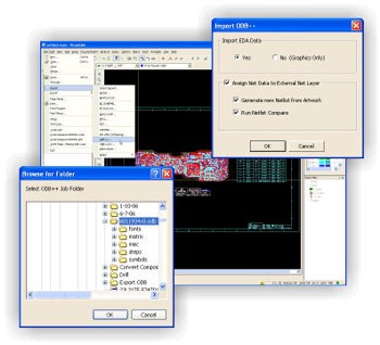
If you are still working with traditional Gerber formats from other systems, then you'll be pleased to find that VisualCAM includes an Import Wizard that goes beyond just importing Gerber data. Using the Import Wizard, you simply direct VisualCAM to the location of your data, and it does the rest by detecting the various file formats(Gerber, Drill, Mill, HPGL, DXF, etc.)automatically. If you still use 274D, it will even detect aperture table formats and convert them as well. VisualCAM also has format-specific interfaces for all supported database types(Gerber, Barco DPF, DXF, HPGL & HPGL/2, Excellon, Sieb & Meyer, IPC-D-356A, etc.), just in case you want to load a single file or re-load existing files.
Optimization
Everything you need to optimize a design for manufacturing is just a mouse-click away with VisualCAM. Functions such as Draw-to-Flash conversion, Teardropping, converting those nasty, special pad shapes(the ones that are always drawn)into flashes, and more. You can even use our Flatten Composite function to eliminate those 274X composites that your CAD system might be outputting.
The Solder Mask Generator and Optimizer create perfect solder mask layers for you, using a comprehensive set of rules that are designed to give you maximum possible clearance while maintaining optimal coverage throughout your design. Special support for fine-pitch pads is provided, with automatic generation of block openings for those areas, to prevent web(sliver)problems between pads. Existing solder mask layers can also be optimized to conform to your rule sets.
The Paste Mask Generator and Optimizer can be appreciated by any Designer or Stencil Manufacturer. Like the Solder Mask Generator, it is driven by a comprehensive set of rules that are designed to give you optimal reduction across a wide variety of pad shapes and sizes. Special support for fine-pitch pads allows independent X and Y reductions, to eliminate paste build-up between pads. If you already have a paste mask layer but are not satisfied with it, the Paste Mask Optimizer will rework it to conform to your rules.
|
HyperNETLIST Generation
VisualCAM provides class-leading performance
with HyperNETLIST generation. Even the
toughest designs can be processed in a matter of
just a few minutes. For example, a 12"x12" 16-layer board with 4mil traces on 4mil spaces can be
processed in approximately 10 minutes on a 3GHz
P4-based PC, as compared to 30 to 45 minutes by
our typical competitor. This kind of performance
puts VisualCAM on par with systems that cost
tens-of-thousands of dollars more.
MCM/LTCC Layer Stack-Up means that you can generate a netlist for your ceramic or foil-based designs. Unlike competitive systems that are limited
to just Gerber layers representing insulators, VisualCAM allows you to specify Gerber or NC layers as insulators, accommodating a wider array
of data input from various CAD systems.
|
 |
Graphical Netlist Comparison
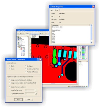
Using VisualCAM's Graphical Netlist Compare, you can finally get feedback that makes sense. Some competitive tools only provide you with a generic, ASCII text report; with VisualCAM, you can see your problems on the screen. Netlist compare finds shorts, opens, nets without copper, missing net points, and test pad size differences. Each violation is easily accessible through VisualCAM's Navigator.
Pin-Point Error capabilities help speed the process of troubleshooting problems. Mere graphical rendering of netlist errors isn't always enough, particularly on more complex nets. VisualCAM can track down the actual location of shorts and opens. The faster you can locate your problems, the sooner you can resolve them and get your design out for production.
External Net access allows you to see, graphically, how a set of external net points compare with an internal net. This information, combined with Pin-Point Errors, can dramatically aid your troubleshooting process.
External Net access allows you to see, graphically, how a set of external net points compare with an internal net. This information, combined with Pin-Point Errors, can dramatically aid your troubleshooting process.
Dynamic DfM Analysis Suite
VisualCAM includes a comprehensive, dynamic analysis "suite", which covers Design Information, Design and Manufacturing Rules Checking, Design for Fabrication, and even Embedded Passive Analysis. You are provided with 75+ checks to help insure that a given design is "manufacturable." The dynamic checklist environment allows for "single-pass" analysis of an entire design, even if you want to check for 5 mil spacing on the top and bottom sides, but need 8 mill spacing on internal layers. Graphical Netlist Comparison, detailed above, rounds out the suite, allowing you to cover all your checking needs in one environment.
|
Design Information Analysis provides
25 "quick" board-level queries. These queries
are used primarily for a broad overview of any
given design for quoting purposes. All queries are reported back on a layer-by-layer basis. Some
of the more popular checks include Minimum
Air Gap, Minimum Trace Width, Hole Counts,
Board Size, and Conductive Layer Count.
Fabricators and Designers will both find these
features particularly useful, for the purposes of
quoting new jobs and putting together a design
summary prior to submitting a job to production.
DRC/MRC Analysis offers checks like
Trace-to-Trace, Trace-to-Pad, Pad-to-Pad,
Drill-to-Pad, Drill-to-Plan, Minimum Trace Width,
Solder Mask Spacing and Annular Ring
Clearances for pads and drills, SMD Pitch &
Spacing, and Silkscreen on Pads.
|
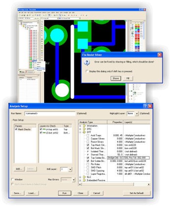 |
DFF Analysis offers manufacturing-oriented checks like Acid Traps, Copper Slivers, Solder Mask Slivers, Solder Mask Bridging, Starved & Isolated Thermals, Pin Hole Detection, Layer Registration, Resist Slivers, and more.
Embedded Passive Analysis provides verification support to the growing Embedded Passive market. Designers no longer need to agonize over a lack of verification capabilities within their CAD systems, when they design with passive resistors. VisualCAM verifies such aspects of passive devices as Resistor-to-Terminator Alignment, Minimum Overlap, Termination Pad Width and Extension, and more. You can work with either Additive or Subtractive passive materials. We've even added utilities for verifying your resistor values, and can output reports designed to help your fabricator during production.
NC Drill & Mill
Our NC Drill and Mill support will finish off your tooling process, with such features as:
Advanced Tool Table Support provides total control over drill charts. Plated and unplated tools are supported, for increased compatibility with today's CAD systems. Mixed tables, supporting both drill and mill tools, can now be generated for increased compatibility with modern NC equipment. Define NC feeds and speeds, as well as plunge and extraction rates, to accommodate a wide range of material usage and stack-up requirements.
Multiple Tool Tables support designs with blind & buried vias. Plated versus non-plated drill layers with separate tool tables can be accommodated, while still maintaining yet another table for milling. Fabricators can have standardized tool tables that are built around their shop floor tooling, and map a customer's tool information to their standard tables with ease.
NC Compensation Index Tables allow you to control the compensation index for each tool, supporting unique requirements such as finish sanding. It also lets the NC operator make minor adjustments at the machine, rather than sending the job back to CAM for reprocessing.
NC Tool Linking & Maximum Hits increases the life of old equipment that does not have automatic tool break detection or automatic linking. Change tools automatically, with no intervention from the operator.
Tool Reordering for Export allows you to change the export order of your tools, to accommodate specific shop processes. Easily adapt a customer-provided tool list to your shop-defined tool list.
User-Defined Break Tabs allow you to build custom break tab libraries that can be saved and reloaded as needed for new jobs. Five different tab types are supported: simple, stitched, double-stitched, crown, and crown break with stitching. Place tabs on linear segments, arcs, or circles -- with or without compensation.
Interactive Milling allows you to create mill paths using standard "draw" and "edit" commands, even using arcs to provide smooth, flowing mill paths on flex designs or irregular-shaped boards. Move data back and forth between Gerber and NC Layers -- VisualCAM automatically makes the translation.
Drilled Text allows you to drill part numbers, job numbers, etc. into your panels, utilizing the "canned" feature within Excellon or Sieb & Meyer format, to allow for automatic compensation of tool size.
Operator Messages & Stop Commands allow CAM operators to stop machines and/or prompt NC operators with specific messages while a job is in process.
|
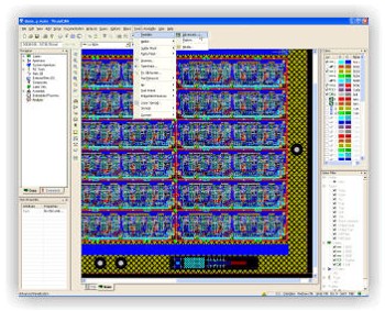
Advanced Panelization
VisualCAM's Advanced Panelization provides
a fully self-contained environment that lets you
store an unlimited number of panel templates.
You can build templates for each of your shop's
standard panel sizes, so you'll never have to
define another panel configuration again!
Multi-job panelization has become more and
more popular for optimizing tooling output for
prototypes, limited piece count production,
and assembly panels.
|
 |
VisualCAM supports stepping and repeating multiple jobs within a single panel. Different Robber(Galvanic)Bars, Venting, and Thieving patterns can be defined for as many layers as necessary, through the use of layer sets. Venting and Thieving supports solid, dot, hatch, and starburst patterns on any layer. VisualCAM can also accommodate positive and negative polarities with ease.
All of these functions perform quickly and efficiently, without the hassle of separate editors, special symbols, and complex user interfaces. Coupons, tooling holes, title blocks, and even your one-up designs are just .VCAM databases. Combine as many as you like, in whatever configuration you like. The possibilities are unlimited!
Test Fixturing
Need to create bare-board fixturing information?VisualCAM includes test fixturing capabilities for both Flying Probe and Bed-of-Nails, unlike the competition who requires you to purchase additional modules for their products. You will find support for multiple pin sizes, double-sided fixturing, test-point staggering, and more. Netlist output is fast and easy, using the industry-standard IPC-D-356A format.
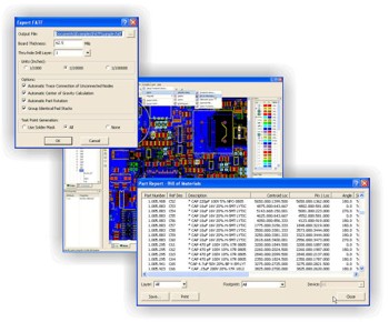
Assembly Reverse Engineering(Optional)
Extracting centroid information from Gerber data has historically been a cumbersome process, prone to great amounts of difficulty and error. Today, VisualCAM streamlines the process with 5 different automated methods for reverse engineering component footprints, providing processing times that range from just tens-of-seconds to tens-of-minutes, depending upon the methodology you choose.
|
|
Component Footprint Library support allows you to load, save, and work with standard footprint libraries that you have built from previous reverse engineering jobs. You may assign Part Numbers, Descriptions, Value, and Tolerance information for any given device that has been created with a given footprint.
IPC-D-356 Identification offers the fastest, most accurate, and highest level of automation for reverse engineering component footprints. Since many design data sets include IPC-D-356 files for verification purposes, VisualCAM allows you to use that same file for a fully-automated reverse engineering flow that can process most jobs in seconds.
|
Centroid Identification is designed for those working with older data sets that may have been previously programmed for assembly, but now the job needs updating and more intelligence is required. VisualCAM can take a pre-existing ASCII centroid report file, and use it to guide you through the reverse engineering process. During the part identification process, a semi-automatic method uses the reference designator and part number or device name from the report file. Most jobs can be processed in a matter of minutes, depending on the number of components.
Silkscreen Identification gives you some amount of automation, even though all you have to work from is basic Gerber data(no IPC-D-356 or centroid files are available). VisualCAM offers a unique Character Recognition feature that automatically converts drawn Reference Designator text to true text, after which the Reference Designators can be used to guide you through the reverse engineering process. While this method is not the most ideal, it still offers a relatively high level of accuracy and throughput -- most jobs can be processed within an hour, depending on the number of components.
Footprint Library Identification is for those who are more interested in using a specific set of footprint definitions from a library that you have built yourself, or obtained from elsewhere. During processing, footprints in the library are automatically sorted from largest to smallest, after which VisualCAM identifies parts on the board in that order. Although the identification process is automated, you must label the footprints manually with this method.
Interactive Identification is provided as a back-up. It is used for building footprint libraries, developing specialized footprint, or filling in where any "holes" may have existed within an IPC-D-356 or centroid file. You can completely reverse engineer a design using interactive identification, however who would want to when you have four other automated methods to choose from?
BOM Import capabilities allows you to put the finishing touches on any assembly reverse engineering process. Oftentimes the IPC-D-356 and/or centroid report files only have enough information present to provide location information. But if you also need to provide part numbers, descriptions, values, and tolerances, then that information typically has to come from a Bill-of-Materials(BOM)file. VisualCAM gives you the ability to import your BOM file after footprint identification is complete, and updates all components on the board with the information found in the BOM.
Automation and Scripting
Automation is the ultimate goal in almost any environment, be it design or manufacturing, and VisualCAM will not let you down. For quick and easy scripting, VisualCAM offers traditional macro records and playbacks. But for more advanced needs, like those of fabrication shops, you will find a full drag-and-drop Macro Developer that allows anyone to produce high quality macros with ease. Our Macro Developer even comes complete with a built-in debugger at no additional charge.
|