| |
Layout-based power-aware signal integrity
Key Benefits
• Performs time domain signal integrity analysis to confirm that designs
meet specified targets
• Documents your simulations with flexible 2D and 3D visualization results
including waveforms and virtual walk-through
• Provides streamlined workflows for layout-based electrical rule checks
(ERCs) using embedded solvers and simulators
Uniquely equipped to let you perform a broad range of analysis tasks from a single
tool—including electrical rule checking, interconnect model extraction, signal integrity
(SI) and power integrity (PI) studies, and design-stage electromagnetic interference
analysis—Cadence® Sigrity™ SPEED2000™ technology is a layout-based finite
difference time-domain (FDTD) simulation tool for IC package and/or board analysis
with multiple workflows to guide the user through the various analysis tasks.
Included is a combination of circuit and transmission-line simulations with a fast,
special-purpose electromagnetic field solver that computes dynamic interactions
between signal, power, and ground on IC package and board signals and planes.
The Sigrity SPEED2000 technology is designed to work with popular chip/package/board
design flows. The tool lets you perform time-domain analysis to confirm that designs
meet specified targets, it understands complex voltage noise propagation (including
return-path discontinuities), simulates simultaneous switching noise (SSN), and
helps you identify improvement opportunities. The Sigrity SPEED2000 technology
provides a transient simulation environment for both SI and PI of package and/or
PCB. Interconnect model extraction can be performed to support reflection-focused
(level 1) or crosstalk-focused (level 2) simulation in a pure circuit simulator such as
the Cadence Sigrity SystemSI™ simulator. In addition, the Sigrity SystemSI and
SPEED2000 technologies can be used together to support detailed power-aware
(level 3) SI analysis using the FDTD-direct workflow.
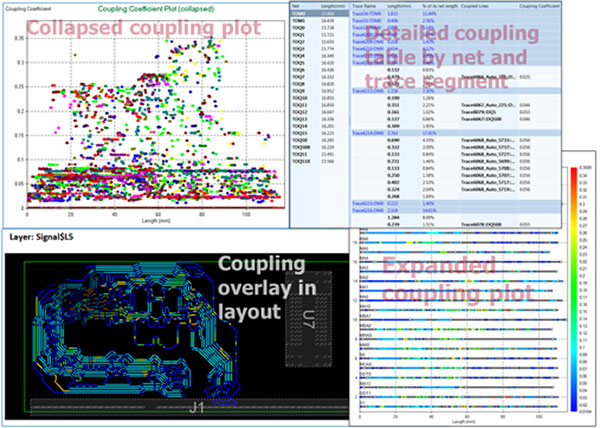
Graphical results from Sigrity SPEED2000 ERC workflows
Another popular Sigrity SPEED2000 workflow is power-aware electrical rule checking
(ERC). This unique technology expands beyond classic impedance and crosstalk rule
checking by including estimated noise coupling from power and ground planes that
may be ringing.
The electro-static discharge (ESD) workflow is used to test the impact of sudden and
unexpected flow of electricity from an external source such as human contact or
plugging in a cable with a charge. The flow includes defining the placement of an ESD
gun model and then observing the impact to the board, signals, and planes.
Transient-voltage-suppression (TVS) diodes and their ability to clamp the voltage peak
are included in the ESD simulation.
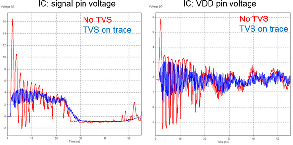
ESD simulation differences with and without transient-voltage-suppression diodes
Features
• Workflows for full board screening of signal impedance, crosstalk, and return
path discontinuities (no models required)
• Simulation-based SI rule checking that considers power plane noise (no models
required)
• Simulates simultaneous switching noise (SSN) and identifies improvement options
• Unique electromagnetic control (EMC) simulation solution with support for designs
with non-linear drivers and receivers
• Determines the impact of variations in stack-up, plane geometries, and I/O
configurations
• Observes where noise is generated, identifies how it propagates, and determines
if it stays within targeted levels
• Interconnect model extraction of single or coupled signal lines for use with external
circuit simulators such as the Sigrity SystemSI tool
• Behaves as an FDTD-direct engine for the Sigrity SystemSI tool, enabling system-level
power-aware SI analysis (no requirement for S-parameters)
• ESD workflow provides feedback on effectiveness of TVS diodes
• Optimized for flows with Cadence SiP Layout, Allegro® Package Designer, and Allegro
PCB Designer
• Readily used in Mentor, Zuken, and Altium flows, accepting a mix of CAD databases
where needed for multi-structure design support
|